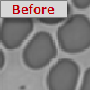

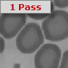
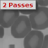

Image Enhance Operations is a collection of Convolutions, Edge Operations, Image Arithmetic and Image Processing algorithms used to enhance image details for identification and measurement.
Convolutions, often referred to as spatial convolutions and filters are multi-pixel operations where the output pixel value is determined by the input values of the surrounding pixels.
Median filters are useful for detecting single point noise pixels and replacing them with a value more similar to the gray level values in the surrounding neighborhood. This can reduce noise spikes, dark or light, without affecting the quality of the image sharpness. Repetitive operations of the Median may not yield much improvement over the first pass.
Smooth filters replace each pixel with the average of its neighbors. This process can be useful in reducing noise speckle in the image when using low light conditions. Effectively the techniques applies a "blur" to the image, making conspicuous pixel intensities merge with their neighbors. This operation can be applied for a multiple number of passes, progressively smoothing the image.
Erode shrinks dark objects by one pixel for each pass applied. This may be used to Erode small dark objects until they disappear so that they will not be detected by Identify and counted later. Shape of objects may change after many passes.
Dilate grows dark objects by one pixel for each pass applied. This can be used after Erode to Dilate objects back to approximately their original shape and size, so that smaller objects will have been removed and will not be detected by Identify and counted later. Shape of objects may change after many passes.


Thicken grows light objects by one pixel for each pass applied, but prevents objects from growing together. Use on samples which have linear objects. Shape of objects may change after many passes.
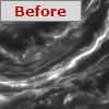

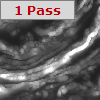
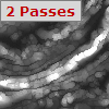
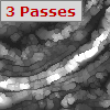
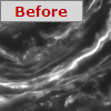
Thin shrinks light objects by one pixel for each pass applied, but prevents objects from disappearing. Use on samples which have linear objects. Shape of objects may change after many passes.

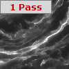
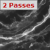
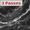
Sharpen increases the contrast between each pixel and its neighbors, giving the image a "sharper" visual appearance. With images containing a degree of noise, the result can be an increase in the sharpness of the noise, making the image useless. This operation may be combined with Smooth or Median to reduce the noise beforehand. A particular application of this operation is for Halo Removal, where different gray phases in an image have some blur at the edges which creates a halo of a different apparent phase. Sharpening the image can remove this Halo to allow separate detection and measurement of the different phases.
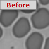

Edges are usually one of the most important features in a microscopic structure, and can often be utilized for measurements after appropriate enhancement algorithms have been applied. These algorithms try to identify points in a digital image at which the image brightness changes sharply or more formally has discontinuities.
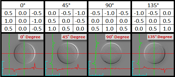
Gradient operators can be used to detect an increase or decrease of gray level intensity in one of four directions:
The result of a Gradient filter is to enhance edges in the image on a pixel by pixel basis. A positive change in gray level intensity in the selected direction will result in a bright pixel value. A negative change in gray level results in a dark pixel value. No change in gray level results in a mid-gray pixel value. Objects frequently will show a bright edge on one side and a dark edge on the other side.
The Kirsch filter shows object boundaries based on their contrast with the background by measuring both positive and negative changes in gray level within the pixel neighborhood in any direction will result in a pixel intensity proportional to the size of the change. No change in gray level results in a black pixel value.
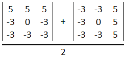
Objects frequently will show a bright edge all around with black inside the object (no change) and black in the background (no change). The Kirsch operator has a more intense reaction to edges than the Morphology, Sobel and Prewitt operators.
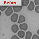

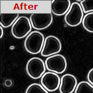
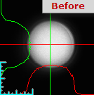

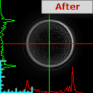
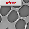
The Morphology operator's reaction to edges is similar to but less intense than the Sobel, Prewitt, and Kirsch operators.
The Prewitt operator's reaction to edges is similar to but more intense than the Morphology and Sobel operators, and less intense than the Kirsch operator.
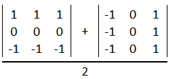
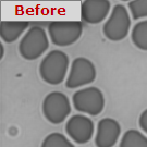

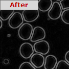


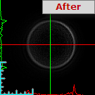
The Sobel operator's reaction to edges is similar to but more intense than the Morphology operator, and less intense than the Prewitt and Kirsch operators.
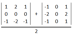
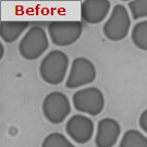

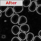


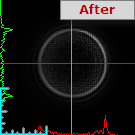
The Laplacian filter like the Kirsch filter, the current display image is enhanced by object boundary intensities shown proportional to the amount of contrast to the background in any direction, but unlike the Kirsch, information on the direction (sign) of the change is retained. A positive change in gradient is indicated by a bright pixel intensity, a negative change has a dark pixel intensity. No change in gray level results in a mid-gray pixel value.
Objects frequently will show both a bright edge and a dark edge all around with mid-gray inside the object (no change) and mid-gray in the background (no change). It is the separation of the direction of gray level change (gradient) that distinguishes the Laplacian operator from the other multi-directional operators, Morphology, Sobel, Prewitt and Kirsch.
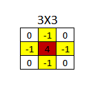
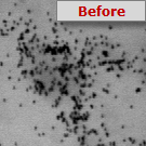

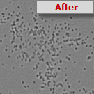


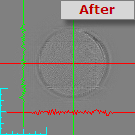
The Laplacian 2 filter is similar to the Laplacian filter but uses a more aggressive kernel.
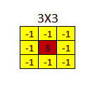


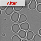


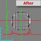
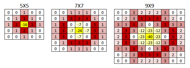
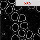
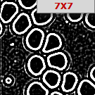
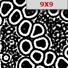
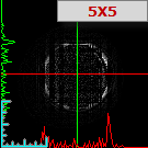
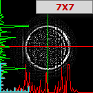
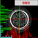
The LofG or Laplacian of Gaussian filter is a two step process in which the image is first smoothed by a Gaussian kernel and then the edges are detected using the Laplacian operator. The response of the smoothing is dependant upon the size of the object and the size of the Gaussian kernel used. Because of this relationship, a 5X5, 7X7 or 9X9 kernel may be selected.




The Canny Edge is a multi-step edge detection algorithm used to detect edges and suppress noise at the same time. The steps involved in this Canny Edge process include:


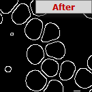


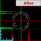
Image arithmetic applies one of the standard arithmetic operations or a logical operator to two or more images. The operators are applied in a pixel-by-pixel fashion which means that the value of a pixel in the output image depends only on the values of the corresponding pixels in the input images. Therefore, it is important that the images are the same size and bit depth but also that they were acquired under the same conditions, i.e., exposure, gain, etc. Hence, the images normally have to be of the same size. One of the input images may be a constant value, for example when adding a constant offset to an image.
Creates a negative of the image. All of the dark areas become light and light areas become dark.
Choose from the list of available Math operation choices for combining the Saved and current images.
Arithmetically combine the current image with the Saved image. The addition of two gray images with gray levels from 0 to 255, creates gray level possibilities from 0 to 510. These values are scaled back into the current display image from 0 to 255, so the resulting image is like a double exposure of the two images.
Arithmetically combine the current image on display with the Saved image. The subtraction of two Grey images with gray levels from 0 to 255, creates gray level possibilities from -255 to 255. These values are scaled back into the current display image from 0 to 255, by scaling gray level -255 equal to 0 (Black) and gray level +255 equal to +255 (white), thus gray level 127, is equal to mid gray, and reflects no change between the two images. The dark and bright portions of the resulting image represent loss or gain in intensity, useful in comparing x-rays, or images taken at different times during the growth of a sample.
Arithmetically combine the current image with the Saved image. The subtraction of two gray images with gray levels from 0 to 255, creates gray level possibilities from -255 to 255. Positive values are scaled back into the current display image from 0 to 255, negative values are truncated to zero intensity.
Arithmetically combine the current image on display with the saved image. The addition of two images with gray levels from 0 to 255, creates gray level possibilities from 0 to 510. Values are NOT scaled back into the current display image, and so bright values may saturate at 255. This can be used as a method of image integration.
This function replaces each pixel in the current image with the Minimum value of the current and saved image. No scaling is applied. This method can be used to create a minimum projection of a series of images, perhaps at different focal depths of a sample.
This function replaces each pixel in the current image with the Maximum value of the current image or saved image. No scaling is applied. This method can be used to create a minimum projection of a series of images, perhaps at different focal depths of a sample.
Each pixel of the current image is added to the value and the result used to replace the pixel in the displayed image. This function may be used to apply a background offset to remove uniform background intensity, or to equalize two images.
Each pixel of the current image has the constant value subtracted and the result used to replace the pixel in the displayed image. This function may be used to apply a background offset to remove uniform background intensity, or to equalize two images.
Each pixel of the current image is multiplied by the constant value and the result used to replace the pixel in the displayed image.
Each pixel of the current image is shifted up by the constant value and the result used to replace the pixel in the displayed image.
Each pixel of the current image is shifted down by the constant value and the result used to replace the pixel in the displayed image.
Allows images to be temporarily saved into memory for the use of applying image arithmetic calculations on two images.
Makes a duplicate copy from the gray image currently on display to memory, replacing any image previously saved by this option
Swaps the saved gray image in memory with the image currently on display.
Copies from the saved gray image currently in memory to the display, replacing the current image on display
Clears all pixels to a zero intensity value.
The saved image can be used for arithmetic combination (Grey Level Math ) with already enhanced images or with a further image loaded in to the current display using Disk Load... The saved image can be returned to the display later by using the Restore option. If the image on display should not be replaced, use the Exchange option.
Note: Only one image can be saved to memory at one time, if logical operations involving more images is required, use File I/O.
Allows Disk Save/Load operations, and can be used to store temporary images to disk for use in the Workfile process. These operations are the only means by which to apply imaging arithmetic calculations involving more than two images. Each File I/O operation is available in both Query mode (interactive, asks for filename) and Fixed Mode (filename is stored and re-used).
Loads an Image from a disk file into the image currently on display.
Note: Image formats will be converted as necessary to fit the target image depth.
Saves the Image currently on display to a disk file.