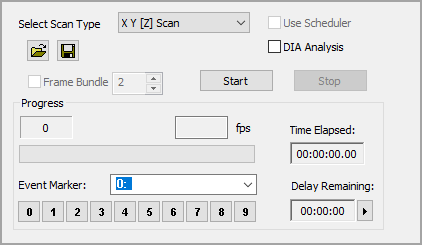
The Multi-site XYZ Scan allows images to be captured for display, archiving or processing, while scanning a two dimensional area with a motorized stage device. This can provide the ability to collect spatial information on static objects outside of a single field of view. To setup a Multi-site scan go to the Sequence pane and select XYZ Scan from the Select Scan Type drop-menu. Once the scan has been setup use the Save Scan icon to save scan settings for repeated use. Use the Open icon to load a saved scan.

Note: Calibration is Very Important!! Prior to adding the scan locations, load the correct spatial scale factor and calibrate the stage. For more information about calibration see "Spatial Calibration."
The Scan Settings panel is easy-to-use, simply set the speed, define the capture interval, enter the number of passes to capture and where to save the data.
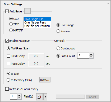
Use AutoSave to define where and how to store acquired data.
Determines how the data is structured when written to a data document.
Determines if a live view is displayed in the image display or if acquired images may be reviewed during the acquisition.
Select the maximum speed or a type of delay.
Defines a specific Frame, Pass or Time point to stop the current scan.
The Auto-focus is used to automatically find the right focus Z at a given X-Y position while acquiring an image sequence. One example is to update the Z position of a field in a time-lapse to allow for Z stage drift. Enter the number of fields to indicate how often to refocus the Z.
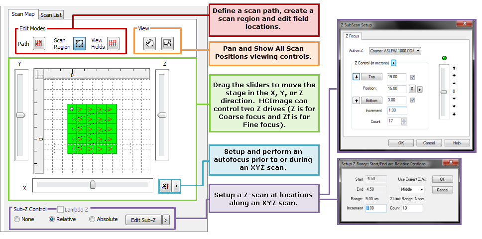
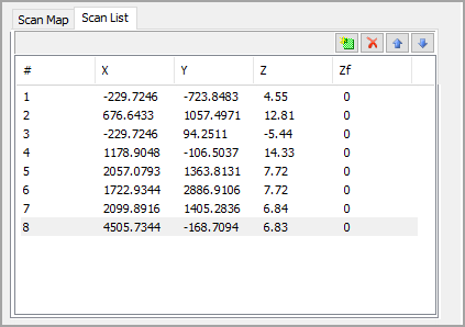
The XYZ Scan Setup panel provides a number controls for setting up simple line scan to complex multidimensional scans. Scan positions are displayed in a 2-dimensional grid view as a Scan Map and as ordered list of X, Y, Z coordinates called the Scan List.

Live Controls are used to navigating and adding positions to a scan, while other controls are used for defining scans and to provide location feedback.
 ) to activate the live feedback mode that provides a live image and displays the current position of the stage. Navigate to points of interests using the stage joystick, the current location is displayed in the scan map and in the coordinates box described below.
The Scan Map displays the coordinates of the current position as indicated by the white dot. The units are determined by the selected calibration. For more information about calibration see "Spatial Calibration." The green rectangles represent a selected location and the white dot indicates the current position. The XYZ coordinates for the current position are displayed above the grid. The red arrows trace the scan path to each of the selected locations. The XYZ Position Sliders allows the XYZ position to be changed by clicking and dragging the slider handle. The movement of the slider is relative, not absolute, so dragging the slider further up or down the scale will produce a faster movement in that direction. Click the Auto-focus icon to have HCImage determine the optimum Z position.
| Icon | Name | Function |
|---|---|---|
|
|
Path | To create the path of travel between View Fields, select the Path button, then left-click on each View Field in turn to link the View Fields together. Click away from a View Field when finished. The path is shown as red connecting arrows. Deselect the Path button when done. |
|
|
Scan Region |
Once all of the fields (locations) have been marked, view fields can be created as a group using Scan Region. |
|
|
View Fields | View Fields can be modified when the Edit View Fields button is pressed . Left-click to select a View Field. The right-click menu contains several options. Also the selected View Field can be dragged to a new position on the slide; to see a live image at the same time in order to better align the View Field with the specimen, or to adjust the focus position. Select the View Field and use the right-click menu option Feedback. This will initiate the Feedback mode and drive the stage to the selected View Field position, displaying the live image in the Image Display. While in this mode the stage movements will move the View Field position and show these changes on the Scan Map. Unpress the Edit View Fields button and the Stage Marker Feedback button when done. |
|
|
Pan | Use Pan to change the field of view. |
|
|
Show All Scan Positions | Use the "Show All" button to fit all of the scan positions in the visible frame. |
The Scan List displays the coordinates for each of the scan positions. The list is interactive, click on a position in the list and the stage will move to that location. See the list below for more information on the interactive scan list.
The Auto-focus is used to automatically find the right focus Z at a given X-Y position prior to acquiring an image sequence. If you wish to perform an auto-focus while acquiring see "Refresh Z Focus (Auto-focus)."
The Sub-Z Control is used to setup a Z scan at points along an XYZ scan. The Lambda Z![]() Is a Z scan for each wavelength or channel; i.e. channel 1 Z scan, channel 2 Z scan, repeat up to 5 channels. option is available when acquiring up to five channels in mono. There are three Sub-Z control options:
Is a Z scan for each wavelength or channel; i.e. channel 1 Z scan, channel 2 Z scan, repeat up to 5 channels. option is available when acquiring up to five channels in mono. There are three Sub-Z control options:
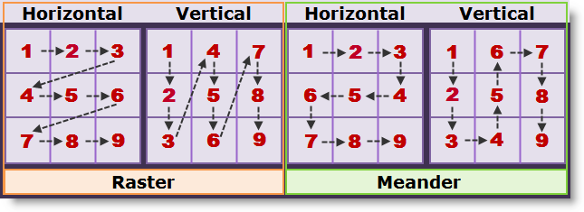
Note: What is the difference between a Raster and a Meander scan? 